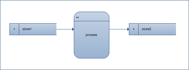
Visio Bowtie diagram stencil and template. A stencil that can be used to create bowtie drawings. The template provides a blank drawing canvas and defines the way connections flow on a drawing. While there are no Sankey Diagrams templates that ship with Visio, there are a few in-the-box shapes that can be used to create rudimentary Sankeys. Visio's Block Diagram Template and Blocks stencil have shapes that you can use to create Sankey diagrams. Table of Visio shapes that map to Process Designer objects for Data flow diagram shapes stencil; Visio Shape Designer Object; Data process: General step: Center to center 1: Route: Center to center 2: Route: Multiple process: Submap step: Loop on center: Nothing: Loop on center 2: Nothing: State: General step: Start state: Start: Stop.
Process flow diagrams. PFDs show how industrial process equipment is interconnected by a system of pipelines. A PFD is more conceptual than a P&ID, and usually includes more annotations that display data. Create a piping and instrumentation diagram. In Visio, open any of the following templates: Piping and Instrumentation Diagram. Click on the images to get a full page view of the individual flowchart templates. There you can download them as images or quickly modify them using the 'Use as Template' button. You can find more flowchart examples in our community and or workflow diagrams examples in this blog post.

You can use a data flow diagram in Visio to document the logical flow of data through a set of processes or procedures. Visio lets you include external sources and destinations for the data, activities that transform the data, and stores or collections where the data is held.
Click the File tab.
Click New, click Software and Database, and then double-click Data Flow Diagram.
From the Data Flow Diagram Shapes stencil, drag an External interactor shape onto the drawing page to represent each external source or destination for data.
Drag more shapes onto the page to represent the processes, states, or entities involved in the data flow you are documenting.
Indicate the flow of data in your diagram with Center to center shapes and indicate data loops using Loop on center shapes.
Indicate data flow between objects
From Data Flow Diagram Shapes, drag a Center to center shape onto the drawing page. Place it near the two shapes between which you want to show the flow of data. Ragnarok patch server status.
To change the direction of the arrow, select the arrow, and then on the Home tab, in the Arrange group, click Position. Point to Rotate Shapes, and then click Flip Horizontal or Flip Vertical.
Drag the endpoints of the Center to center shape to the connection points at the center of each of the other shapes. The endpoints turn red to indicate that the shapes are connected.
To change the arrow curvature, drag the selection handle . To change the location of the ends of the arrows, drag a control handle .
Since DWG TrueView also includes basic markup, measuring, and some tracking capabilities, you may want to try that freebie first to see if you even need to buy Bluebeam Revu. Bluebeam pdf review software.
Indicate a data loop
From Data Flow Diagram Shapes, drag a Loop on center shape onto the drawing page near the place where you want to indicate a data loop.
Drag the begin point of the Loop on center shape to the center of the state or process shape that has the data loop. The endpoint turns red to indicate that the shapes are connected.
To change the size or position of the loop, drag the end point. To change the location of the ends of the loop, drag the control handle and the selection handle . Bootrec rebuildbcd total identified windows installations 0.

From the Data Flow Diagram Shapes stencil, drag an External interactor shape onto the drawing page to represent each external source or destination for data.


Examples Of Visio Diagrams
Free Visio Stencil Download
- Example of document conversion from Visio to ConceptDraw Data Flow Diagrams Software; UML Diagrams Software; Vector Drawing Tools; Cross Platform Visio Data Flow Diagram Template Download.
- By Creately Templates. Data Flow Diagram Template for Creating Your Own Data Flow Diagrams. Tagged: dfd,dataflow,data flow diagrams,dataflow templates,data flow templates,dfd templates.
You can design data flow models using the Data Flow Model Diagram template, which includes shapes for all the symbols used in the Gane-Sarson notation.
The Data Flow Model template uses a top-down design strategy for creating data flow diagrams. You begin by creating top-level processes. Then you decompose each process into subprocesses for more detail.
Visio 2010 Data Flow Diagram Stencil Download
Microsoft Visio Stencil Download

You can use a data flow diagram in Visio to document the logical flow of data through a set of processes or procedures. Visio lets you include external sources and destinations for the data, activities that transform the data, and stores or collections where the data is held.
Click the File tab.
Click New, click Software and Database, and then double-click Data Flow Diagram.
From the Data Flow Diagram Shapes stencil, drag an External interactor shape onto the drawing page to represent each external source or destination for data.
Drag more shapes onto the page to represent the processes, states, or entities involved in the data flow you are documenting.
Indicate the flow of data in your diagram with Center to center shapes and indicate data loops using Loop on center shapes.
Indicate data flow between objects
From Data Flow Diagram Shapes, drag a Center to center shape onto the drawing page. Place it near the two shapes between which you want to show the flow of data. Ragnarok patch server status.
To change the direction of the arrow, select the arrow, and then on the Home tab, in the Arrange group, click Position. Point to Rotate Shapes, and then click Flip Horizontal or Flip Vertical.
Drag the endpoints of the Center to center shape to the connection points at the center of each of the other shapes. The endpoints turn red to indicate that the shapes are connected.
To change the arrow curvature, drag the selection handle . To change the location of the ends of the arrows, drag a control handle .
Since DWG TrueView also includes basic markup, measuring, and some tracking capabilities, you may want to try that freebie first to see if you even need to buy Bluebeam Revu. Bluebeam pdf review software.
Indicate a data loop
From Data Flow Diagram Shapes, drag a Loop on center shape onto the drawing page near the place where you want to indicate a data loop.
Drag the begin point of the Loop on center shape to the center of the state or process shape that has the data loop. The endpoint turns red to indicate that the shapes are connected.
To change the size or position of the loop, drag the end point. To change the location of the ends of the loop, drag the control handle and the selection handle . Bootrec rebuildbcd total identified windows installations 0.
From the Data Flow Diagram Shapes stencil, drag an External interactor shape onto the drawing page to represent each external source or destination for data.
Examples Of Visio Diagrams
Free Visio Stencil Download
- Example of document conversion from Visio to ConceptDraw Data Flow Diagrams Software; UML Diagrams Software; Vector Drawing Tools; Cross Platform Visio Data Flow Diagram Template Download.
- By Creately Templates. Data Flow Diagram Template for Creating Your Own Data Flow Diagrams. Tagged: dfd,dataflow,data flow diagrams,dataflow templates,data flow templates,dfd templates.
You can design data flow models using the Data Flow Model Diagram template, which includes shapes for all the symbols used in the Gane-Sarson notation.
The Data Flow Model template uses a top-down design strategy for creating data flow diagrams. You begin by creating top-level processes. Then you decompose each process into subprocesses for more detail.
Visio 2010 Data Flow Diagram Stencil Download
Microsoft Visio Stencil Download
The bard's tale trilogy download for mac torrent. Note: For information about the Gane-Sarson method, see 'Structured Systems Analysis: Tools and Techniques', by C. Gane and T. Sarson (New York: IST, Inc., 1977). Also see 'Conceptual Database Design', by Carlo Batini, Stefano Ceri, and Shamkant B. Navathe (Redwood City, Ca.: The Benjamin/Cummings Publishing Company, Inc., 1992).
Free Visio Stencils
Visio 2010 Data Flow Diagram Stencil Download
Add Stencils To Visio
Start Visio.
In Visio 2016 and newer versions: Click Templates > Software and Database > Data Flow Model Diagram.
In Visio 2013: Click Categories > Software and Database > Data Flow Model Diagram.
In Visio 2010: Under Template Categories, click Software and Database and then click Data Flow Model Diagram.
In Visio 2007: On the File menu, point to New, point to Software and Database, and then click Data Flow Model Diagram.
Create the top-level detail page for the diagram by dragging Interface and Process shapes from Gane-Sarson onto the drawing page.
Note: In this template, you must use a top-down design strategy for your data flow model diagram. Start the model at the top level and drill down to lower levels.
Connect Interface, Process, and Data Store shapes to each other using Data Flow connectors.
Add a detail page for each process. Your detail pages can include subprocesses that require additional detail pages.
Continue adding detail pages for each process (including interface, process, and data store shapes as needed, connected by data flows) until you have described the entire data flow model system in sufficient detail.
